Saturday, 3 May 2014

High speed flash

High speed flash


Robotic CommuniToy Cameras....

Slot Camera

Photographs taken through a slot and a stepping motor
grater than one
light capture
Self Portrait

Spiral

Robotic CommuniToy Cameras

Friday, 2 May 2014

Robotic Toys


Built to go fast with CD wheels

Robotic Toys


The Objective was to combine the toy hacks with a motorised chassis that enhanced the overall aesthetic and the fun element of the project as well as learning something about basic soldering and building structures that support and allow functionality,


The main criteria was
  • To design a basic structure that needed no gluing and could accommodate a variety of toy sizes
  • A structure that was easy to assemble for children 8 to 14 years old with the minimum of help from adults.
  • It should be powered by a battery.
  • Costs should be kept to a minimum but not so as to compromise the integrity of the finished structure.
  • It must work in the way intended.
  • Must include as much recycled or recyclable material as possible.


We  decided on three basic structures and concepts and allowed the children to choose which one they wanted to make given all the constraints and benfits.


Structure 1
Jitter Bug


Bounces up and down when turned on.


Structure 2
Family Saloon


Large platform for large flat bottomed toys.

Structure 3

Need for Speed


One of the final Robotised toy hacks


Robotic CommuniToys
CommuniToy Kits

The Light Theremin

The Light Theremin


An Astable Circuit
Components
  1. Battery Clip
  2. 2 NPN Bipolar Transistors
  3. Non electrolytic Capacitor 300nF
  4. Non electrolytic Capacitor 100nF
  5. 470Ω Resistor
  6. 5mm Red Light Emitting Diode (led)
  7. 1MΩ Potentiometer
  8. 64Ω Loud Speaker
  9. Light Dependant Resistor (ldr)
  10. Red Lead
  11. Yellow Lead
  12. Red and Blue striped lead


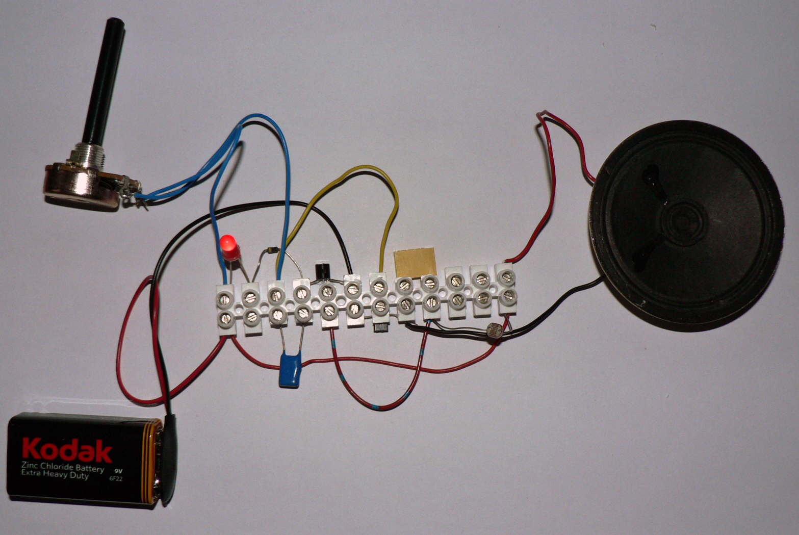
Stages in assembly
  1. Bend the outer legs of the transistor GENTLY out to form this shape:
With the flat side of the transistor facing you the legs are
Topmost COLLECTOR must face positive end of circuit
Middle BASE will take the signal from the switching wire (one only)
Bottom EMITTER must face negative end. A Transistor is a semiconductor and will conduct (Pass) current in one direction only.


Place the transistors so the one on the LEFT has the curved face pointing upwards and the one on the RIGHT has the flat side facing upwards.
The two emitters will be opposite each other then push the negative (black) end of the battery clip in and SCREW UP.
Push the 300nF Yellow capacitors into the gap provided and SCREW UP the two screws adjacent to the capacitors only.
On the opposite side to the capacitor where the collector leg of the transistor is in the hole push in one end of the resistor and SCREW UP.
Next hole push in one lead to the potentiometer and the yellow wire, then SCREW UP this screw .
Next hole the other end of the resistor and the SHORTER leg of the led and SCREW UP both screws.
Next hole push in the longer leg of the led, the other lead for the potentiometer, the red lead to the battery clip and the red wire, and SCREW UP both screws.


Push the yellow wire into the BASE hole (middle leg) for the transistor on the right and then SCREW UP both screws.
Use the Red and Blue striped or yellow wire to connect the BASE of the Transistor on the left and SCREW UP both screws. Take the other end and push into the hole to the right of the capacitor but do not screw up yet.


Push one wire of the LDR into the hole where you have pushed the end of the striped lead and SCREW UP.
Push the black lead of the loudspeaker into the hole opposite the left hand leg of the capacitor ans SCREW UP.
Push the end of the LDR, the end of the red wire and the red lead to the loudspeaker into the final hole and SCREW UP both screws


Go along the circuit gently pulling at all the leads and components to ensure they are firmly secured.

Plug in the battery and ENJOY!
CommuniToy Kits

Toy Piano

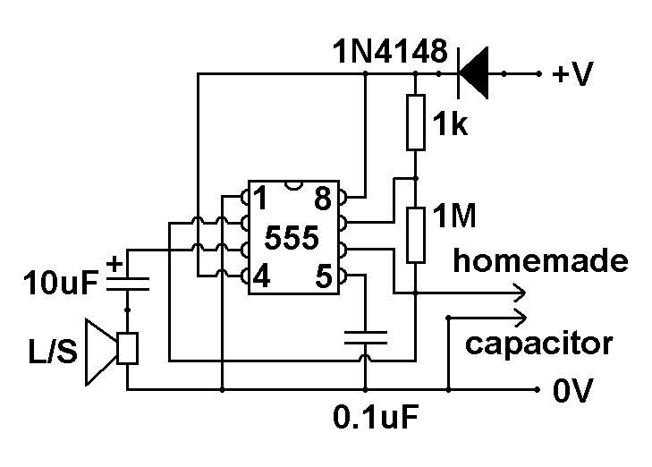
555 astable Toy Piano


The Purpose: To construct a very inexpensive 'piano' that could be assembled by enthusiastic 11 to 14 year olds that could 'play' an octave using a few fixed resistors, capacitors, a 555 timer clip, and a battery.
The Method:


An 555 astable circuit gives a pulsed digital output. Astable means that the 555 can operate repeatedly, it will switch on, then off, then on, then off, continually. The 555 astable may be called an oscillator. The positive output, mark, produces a beep on a loudspeaker followed by a period of silence, the space. When the resistance between pins seven and six are altered or the capacitance between pin 2 and the negative rail is changed, the ratio of time between each mark and space is altered and the period for them to exist in time may be extended or shortened. We hear musical notes because the energy is carried in 'waves' of compression that correspond to the vibration of the loudspeaker's cone that in turn vibrate the ear drum and stimulate the perception of sound. Each musical note is differentiated by its frequency which is the number of times per second that the mark and space are generated per second.
The frequency of the 555 astable oscillator can be worked out by the formula f = 1.44 / (R1 + 2R2) x C . In the example above R1 is 1,000Ω  R2 is 500Ω and C is 0.000001 Farads. F = 1.44/ 1000 + 1000X0.000001 which is 720Hz. The frequencies for equal-tempered scale, A = 440 Hz and this is the note an orchestra normally tunes to.
The 555 shortcomings:  The 555 is a very reasonably priced timer clip, it is robust and in its CMOS form, the 7555, it can be run at very low currents. It produces for this project a high volume output compared to other oscillator solutions such as transistors, op amp, or logic chip. However it is not the most accurate timer chip and can produce slight variances throughout the frequency range and struggles in high capacitance situations. Capacitors have tolerance values of up to 10% so in choosing one test it to ascertain its true initial capacitance. Resistors have inherent tolerance values and the resistance will change with temperature. So the theory is all very good but test the outcome frequency with some kind of chromatic tuner such as the Korg CA-30.
The other problem is that the square wave output sounds very beepy but you can smooth out the square wave with a series is three capacitors and drop down resistors, However this reduces the volume so you may need to build an amplifier.

CommuniToy kits

Mind control

Mind Control Scalextric


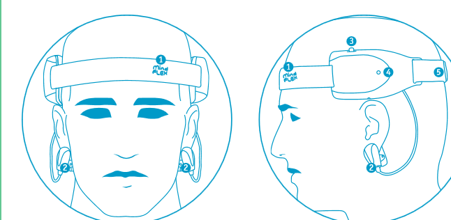
The Purpose: who has not always wanted to make things move with their mind- we can not all be Yoda and lift X-Wings out of the swamp but we can use our minds to move a blue foam ball through a plastic obstacle course thanks to the Mindflex game from Mattel. We found the game element a little lame for such an exciting concept so we decided to redesign the play element of the Mindflex product by making an outcome that was more fun and exciting.
The Mindflex shortcomings: The Mindflex EEG headset 'reads' brain activity by detecting through electrodes attached to the head the potential differences between levels of 'brain wave' activity. It amplifies the small potential differences and transmits the signal by remote control. The Mindflex receiver encodes any exponential intensity of the signals from the headset (greater brain activity) into an increase of electrical power that increases the speed of the fan and the movement of the blue foam ball. Why not connect the output of the Mindflex headset to a controller for a scalextric track and use that power to drive a car round the circuit – the greater the concentration the faster the speed.
The Design Method: Costs - our solution had to be the most affordable solution and use as much as the original gear as possible.
Simplicity in Design – The Mindflex construction contained all the elements to enable redesigning there just had to be a way to link the outcome from the encoder box to replace the hand control from the scalextric.
Working method: Removed the fan mechanism and connected the output to relays that control a series of resistors that control the speed of the cars the same way as it used to control the speed of the fan.
Scalextric shortcomings: we are using the micro Scalextric and the contacts and connections can be poor leading to cars stopping and failing to start correctly. We need to obtain a more reliable set up and leave it assemble ready for use.


Robotic CommuniToy
CommuniToy Kits

noise generator

555 Capacitor and Box


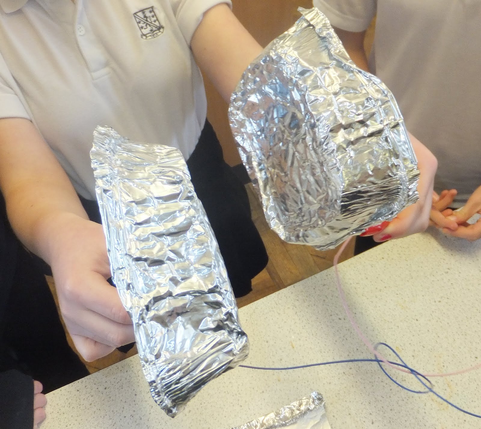
The Capacitor in the 555 astable oscillator circuit
Capacitors are components that are used to store an electrical charge and are used in timer circuits. A capacitor may be used with a resistor to produce a timer.
When power is supplied to a circuit that includes a capacitor - the capacitor charges up.
When power is turned off the capacitor discharges its electrical charge slowly.
A capacitor is composed of two conductors separated by an insulating material called a DIELECTRIC. The dielectric can be paper, plastic film, ceramic, air or a vacuum. The plates can be aluminium discs, aluminium foil or a thin film of metal applied to opposite sides of a solid dielectric. The CONDUCTOR - DIELECTRIC - CONDUCTOR sandwich can be rolled into a cylinder or left flat

Robotic CommuniToy
CommuniToy Kits