The Light Theremin
An Astable Circuit
Components
- Battery Clip
- 2 NPN Bipolar Transistors
- Non electrolytic Capacitor 300nF
- Non electrolytic Capacitor 100nF
- 470Ω Resistor
- 5mm Red Light Emitting Diode (led)
- 1MΩ Potentiometer
- 64Ω Loud Speaker
- Light Dependant Resistor (ldr)
- Red Lead
- Yellow Lead
- Red and Blue striped lead
Stages in assembly
- Bend the outer legs of the transistor GENTLY out to form this shape:
With the flat side of the transistor facing you the legs are
Topmost COLLECTOR must face positive end of circuit
Middle BASE will take the signal from the switching wire (one only)
Bottom EMITTER must face negative end. A Transistor is a semiconductor and will conduct (Pass) current in one direction only.
Place the transistors so the one on the LEFT has the curved face pointing upwards and the one on the RIGHT has the flat side facing upwards.
The two emitters will be opposite each other then push the negative (black) end of the battery clip in and SCREW UP.
Push the 300nF Yellow capacitors into the gap provided and SCREW UP the two screws adjacent to the capacitors only.
On the opposite side to the capacitor where the collector leg of the transistor is in the hole push in one end of the resistor and SCREW UP.
Next hole push in one lead to the potentiometer and the yellow wire, then SCREW UP this screw .
Next hole the other end of the resistor and the SHORTER leg of the led and SCREW UP both screws.
Next hole push in the longer leg of the led, the other lead for the potentiometer, the red lead to the battery clip and the red wire, and SCREW UP both screws.

Push the yellow wire into the BASE hole (middle leg) for the transistor on the right and then SCREW UP both screws.
Use the Red and Blue striped or yellow wire to connect the BASE of the Transistor on the left and SCREW UP both screws. Take the other end and push into the hole to the right of the capacitor but do not screw up yet.
Push one wire of the LDR into the hole where you have pushed the end of the striped lead and SCREW UP.
Push the black lead of the loudspeaker into the hole opposite the left hand leg of the capacitor ans SCREW UP.
Push the end of the LDR, the end of the red wire and the red lead to the loudspeaker into the final hole and SCREW UP both screws
Go along the circuit gently pulling at all the leads and components to ensure they are firmly secured.
Plug in the battery and ENJOY!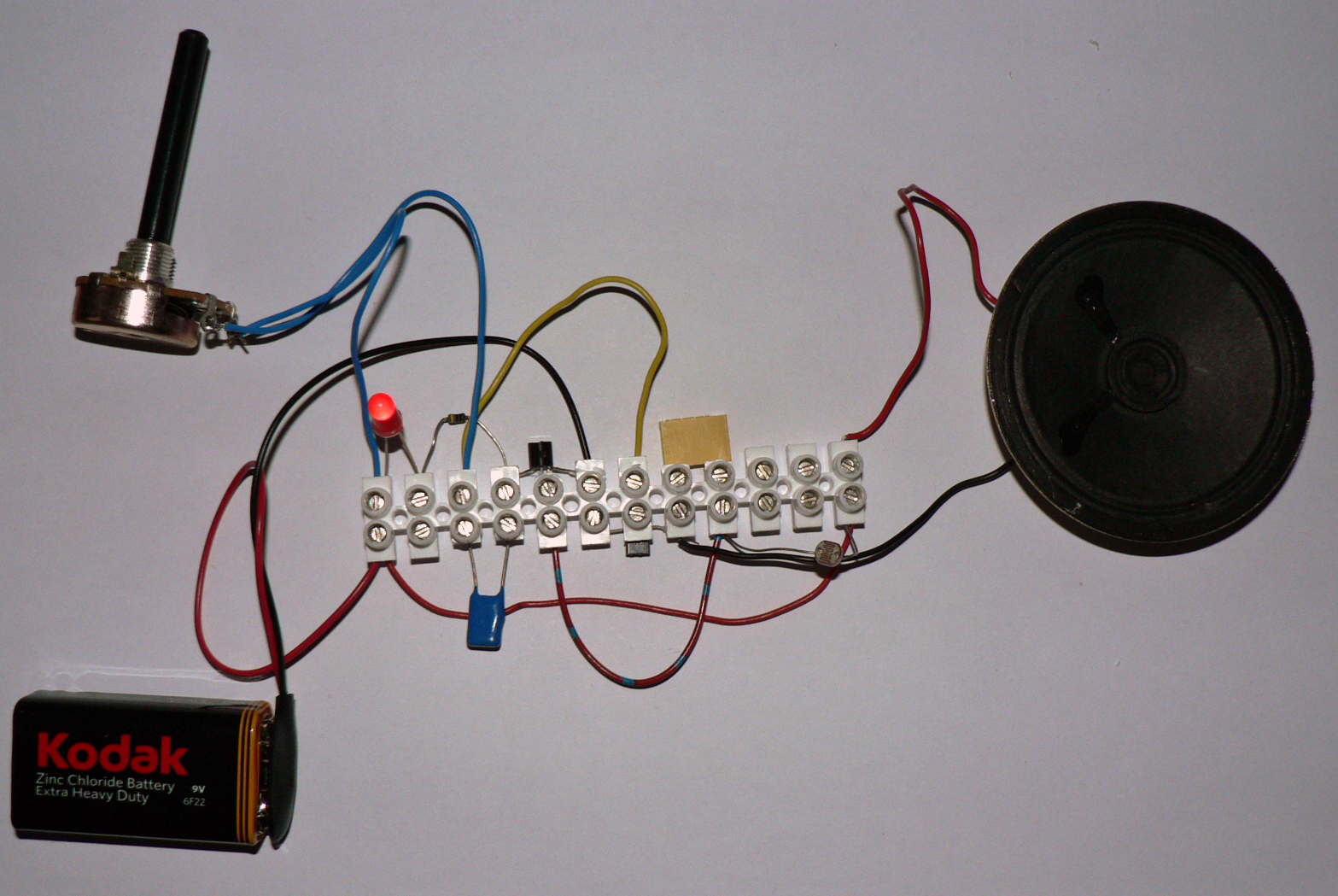
CommuniToy Kits
CommuniToy Kits
No comments:
Post a Comment